ALUMISSION INSTALLATION GUIDE

How to install an aluminum pedestrian gate.

Build a clean, modern entrance with your Alumission single-swing gate kit. Learn how to measure and cut the slats, mount the side posts, assemble the frame, hang the gate and fit the lock.

No-weld kit assembly12 illustrated steps42 answers by topic

For side-yard, garden and residential walk-through entrances. Confirm your kit, supporting structure and hardware before cutting.

WATCH BEFORE YOU BUILD

Follow the complete Alumission gate installation video.

See the actual kit assembled and installed, from preparing the posts to adjusting the hinges and latch. The cover below shows the kit and the finished black horizontal gate from this video.

Approximately 15 minutes · Alumission USA · Chapter links open the relevant point on YouTube.

PACK FOR THE WHOLE INSTALLATION

Tools, equipment and protective gear.

Prepare for metal cutting, post fixing, gate alignment and lock installation—not just the slat assembly. Match every bit, blade and fixing to the actual parts and substrate.

Measure & align

  • Tape measure, pencil or fine marker
  • Long spirit level and quick square
  • Plastic shims for post alignment and gate support
  • Clamps, padded work supports and a helper for lifting

Cut & finish aluminum

  • Miter saw with a compatible non-ferrous aluminum blade
  • Circular or table saw with an aluminum-rated blade if a slat needs ripping
  • Suitable grinder for the outward-opening stopper notch
  • Deburring file, masking tape and compatible touch-up finish

Drill the posts

  • Drill/driver and correct Phillips driver bits
  • 3/4-inch hole saw or metal bit for access holes in the first wall
  • Metal drill bits sized for the specified fixing holes; the video shows 1/8–1/4 inch
  • Hammer drill and matching masonry bits only where the substrate requires them

Fit hinges & stops

  • 1/8-inch metal pilot bit for the demonstrated hinge connection
  • Hinge adjustment hex key and retaining pins supplied with the hinges
  • Countersink bit or suitable larger metal bit for stopper screw-head pockets
  • Rubber mallet and stable temporary gate supports

Install the lock

  • Door-lock drilling jig suitable for the selected frame and lock
  • For the video’s lock: 2-1/8-inch face hole saw and 1-inch latch hole saw
  • Jig set to the video’s 2-3/8-inch backset; verify your lock template
  • Small pilot bit and screwdriver for the lock and strike screws

Protect yourself & the finish

  • Eye and hearing protection for cutting and drilling
  • Handling gloves for sharp edges; follow power-tool glove restrictions
  • Suitable footwear and task-appropriate dust protection
  • Padded assembly surface, chip brush and clean cloths

PLAN THE FIT FIRST

A smooth swing starts with the opening.

  • Verify the supports: confirm the columns or posts and their connections can carry the gate.
  • Choose the swing: check hinges, stopper location, nearby walls and the full ground sweep.
  • Measure after mounting: record the clear width between the installed side posts at top and bottom.
  • Plan the lock: confirm backset, bores, handing and outdoor suitability before drilling.
  • Check special requirements: pool barriers, required exits and accessible routes need the appropriate hardware and layout.

Check your parts before starting.

Compare the order’s component list with the kit on site: side posts and caps, gate frames and covers, slats, spacers, hinges and fasteners, lever hardware and stopper profiles.

Quantities depend on the selected style and size. The video supplies two stopper options but uses the one that matches the swing. Site-specific anchors, tools and the door-lock drilling jig should be planned separately.

Still choosing your gate?

Compare slat patterns, privacy and finishes, then select a kit that fits your opening.

Explore single swing gate kits

FROM BOX TO FINISHED ENTRANCE

Install your aluminum pedestrian gate in 12 steps.

Follow the supplied video and your current kit instructions together. These 3D-style schematics explain the assembly relationships; they are not scaled shop drawings or anchor designs.

ALUMISSION · ASSEMBLY DETAIL 01
Illustrative assembly detail · Watch from 0:00

STEP 01

Confirm the kit, swing and supports.

Lay out the side posts, gate frames, covers, caps, slats, spacers, hinges, lock and both stopper profiles. Select inward or outward swing before cutting. Check the supporting columns or posts, opening limits and clearance over the complete swing path.

Before moving on: Check your exact order; component counts and hinge requirements vary with kit size.

ALUMISSION · ASSEMBLY DETAIL 02
Illustrative assembly detail · Watch from 1:53

STEP 02

Cap, cut and drill the side posts.

Fit the lower side-post caps with the specified #8 screws, then cut the opposite ends to height. The video makes 3/4-inch access holes through the channel-side wall only, with smaller fixing holes through the back wall. It demonstrates four to five locations; your actual fixing arrangement must suit the support and anchors.

Before moving on: A large access hole and a structural anchor hole serve different purposes.

ALUMISSION · ASSEMBLY DETAIL 03
Illustrative assembly detail · Watch from 2:45

STEP 03

Anchor both posts plumb and aligned.

Position each side post, check both directions with a level and mark the fixing positions. Drill the supporting surface using the correct method and install the specified screws or anchors. Use suitable shims where needed; keep the receiving posts aligned and the opening consistent at top and bottom.

Before moving on: Confirm the support and anchorage before hanging the gate; cladding alone is not a structural fixing.

ALUMISSION · ASSEMBLY DETAIL 04
Illustrative assembly detail · Watch from 3:24

STEP 04

Choose the correct cover and stopper.

Fit the hinge-side post cover. For the inward-opening arrangement shown, install the side-post stopper on the latch side. For outward opening, use post covers on both sides and fit the gate-frame stopper later. Cut and slide the profiles carefully, then fit the side-post top caps.

Before moving on: Only one of the two stopper profiles is used for the demonstrated swing arrangement.

ALUMISSION · ASSEMBLY DETAIL 05Measure between side postsSlat length = opening − 8″
Illustrative assembly detail · Watch from 4:26

STEP 05

Prepare the frames and cut the slats.

Temporarily insert the frame covers, fit the lower caps and tape the covers in place for cutting. The video cuts the frames 1–2 inches shorter than the side posts to provide ground clearance; an uphill swing can need more. Remove the covers afterward. Measure between the installed side posts and cut the slats 8 inches shorter for this system.

Before moving on: Use the corrected 8-inch allowance; do not measure from the outside of the columns.

ALUMISSION · ASSEMBLY DETAIL 0690°Seat fully, then fasten
Illustrative assembly detail · Watch from 5:57

STEP 06

Square and secure the first slat.

Work on a padded, stable surface. Seat the first slat fully into both frame channels against the fitted caps. Hold each corner at 90 degrees with a quick square and fasten the slat through the assembly channels as demonstrated, using two #8 screws at each end.

Before moving on: An accurate first connection establishes the shape of the gate.

ALUMISSION · ASSEMBLY DETAIL 07
Illustrative assembly detail · Watch from 6:29

STEP 07

Stack the slats and finish the leaf.

Support the assembly upright and add the selected slats and spacers in their intended order. Seat each component without leaving unintended gaps. If the final slat needs a lengthwise cut, mark it, clamp and protect it, then use a suitable aluminum-cutting setup. The video caps the assembly and flips it so the cut/open edge finishes at the bottom.

Before moving on: Check the full video for orientation before ripping a slat or fitting the final caps.

ALUMISSION · ASSEMBLY DETAIL 08
Illustrative assembly detail · Watch from 7:44

STEP 08

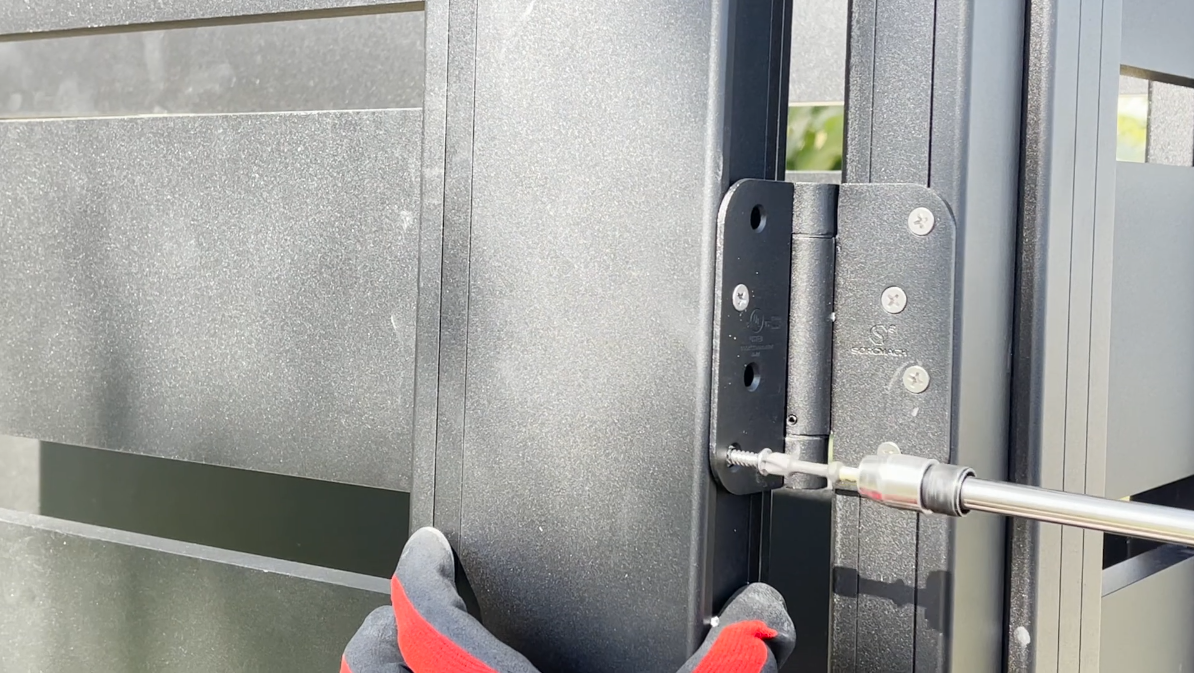
Fit hinges and hang the supported gate.

Locate the hinges for the supplied hardware; the video places them within 12 inches of the top and bottom, with adjustment holes upward. Add the required center hinge for the applicable larger kit. Attach to the side post, hold the leaf at about 90 degrees open on stable shims, and connect the hinges to the frame.

Before moving on: Keep a helper or secure support in place until every hinge connection is complete.

ALUMISSION · ASSEMBLY DETAIL 09
Illustrative assembly detail · Watch from 8:52

STEP 09

Adjust the gaps, then secure the slats.

Support the latch side before loosening assembly screws. Follow the video’s adjustment sequence, retaining the lower hinge-side reference connection. Align the frame and an even latch-side gap—the video uses about 1/4 inch—then refasten through fresh holes as instructed. It recommends slat fixing intervals of 6–12 inches. Refit the frame covers and caps.

Before moving on: Remove temporary supports and test the complete swing before drilling the lock.

ALUMISSION · ASSEMBLY DETAIL 102-1/8″ face bore1″ latch bore2-3/8″ backset in this video
Illustrative assembly detail · Watch from 10:11

STEP 10

Drill and install the lever and strike.

Choose the lock position and follow its supplied template. For the demonstrated lock, use a 2-3/8-inch backset, a 2-1/8-inch face bore and a 1-inch latch bore. Fit the lever, mark the latch location on the receiving post and prepare the strike. Pilot-drill for the supplied lock screws; do not assume they are self-drilling.

Before moving on: Backset is the distance from the latch edge to the bore center, not the hole diameter.

ALUMISSION · ASSEMBLY DETAIL 11
Illustrative assembly detail · Watch from 12:17

STEP 11

Set closing tension and finish the stop.

Use the hinge’s supplied adjustment key and pins according to its instructions. For outward opening, cut the gate-frame stopper to length and notch it around the latch using a properly supported cutting setup. Deburr and touch up the cuts, drill the fixing holes and countersink the screw-head pockets before fastening the stopper.

Before moving on: The stopper must clear the latch and allow the gate to reach its closed position.

ALUMISSION · ASSEMBLY DETAIL 12
Illustrative assembly detail · Watch from 14:15

STEP 12

Test, inspect and enjoy the entrance.

Open and close the gate repeatedly, including from partly open positions where self-closing is required. Check ground clearance, consistent gaps, lever action, strike engagement, stop contact, caps and all fixings. Remove chips and clean the finish. Photograph the installation and keep the kit and hardware instructions for future adjustment.

Before moving on: A pool barrier or required exit needs its own compliance check; ordinary operation alone does not establish approval.

MEASURE TWICE · CUT ONCE

Keep these gate measurements separate.

Slat cutting reference

Slat length = clear opening between installed side posts − 8 inches.

This is the corrected allowance for the Alumission assembly shown. The video’s example is 65-3/4″ − 8″ = 57-3/4″. It illustrates the calculation, not the fitting limit of every kit.

Measure the actual installed opening. Do not substitute the raw column opening, nominal order width or an older 7-3/4-inch instruction. Test one piece and confirm your current profiles before batch cutting.

Lock drilling reference

Video’s lock detailMeasurement
Backset: latch edge to bore center2-3/8″
Large face bore2-1/8″
Latch bore1″

These dimensions describe the demonstrated lock. Follow the actual lock template and verify the frame before drilling.

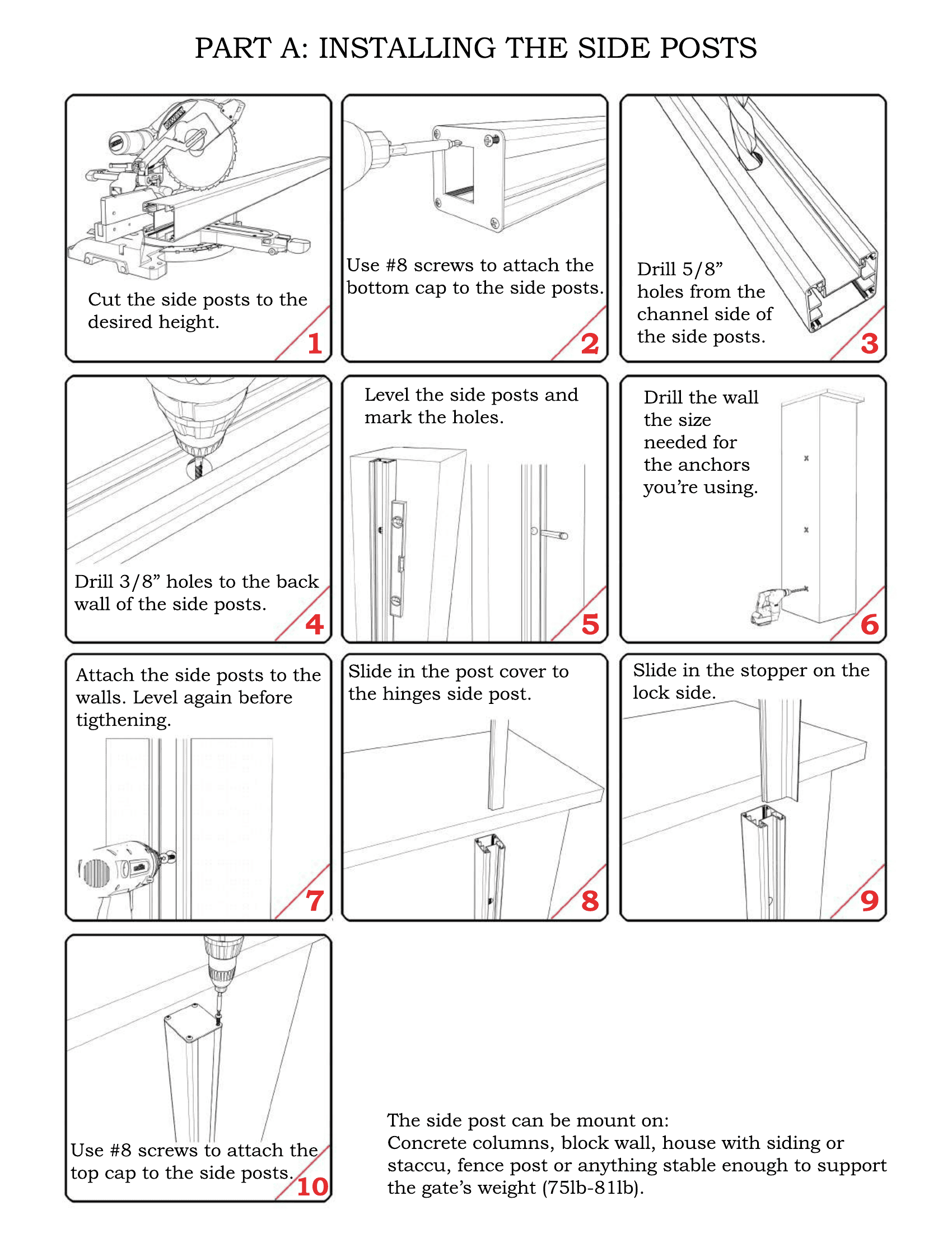
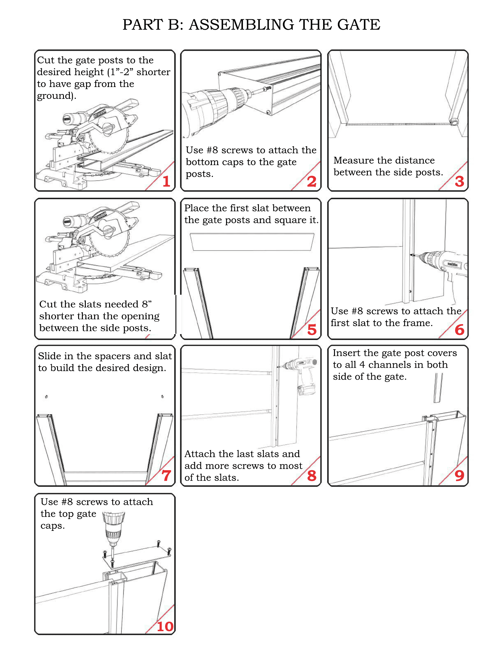
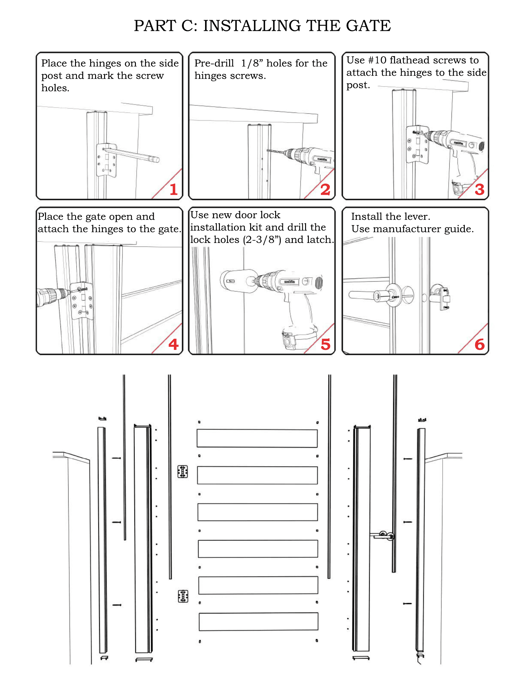
Open the corrected illustrated assembly guide.

Read all four pages in order. The current Part B, Stage 4 uses the 8-inch slat allowance.

Corrected Alumission gate installation guide, page 1 of 4
View page 1 of 4
Corrected Alumission gate installation guide, page 2 of 4
View page 2 of 4
Corrected Alumission gate installation guide, page 3 of 4
View page 3 of 4
Corrected Alumission gate installation guide, page 4 of 4
View page 4 of 4
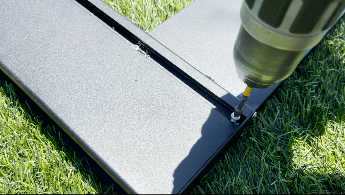
Fastening the first aluminum gate slat through the frame channel
First-slat connection through the assembly channel.
Attaching the aluminum gate frame to its hinges
Hinge installation detail from the Alumission assembly guide.

FIND THE ANSWER FOR YOUR INSTALLATION

Aluminum pedestrian gate installation FAQs.

Browse six topics or search for “slat length,” “hinge,” “backset,” “stopper” or “sag.”

42 questions in 6 categories

Planning & choosing a kit

What does this pedestrian gate installation guide cover?

It covers field assembly and installation of the Alumission horizontal aluminum single-swing gate shown in the video, including side posts, slats, hinges, lock and stopper. Use your selected kit’s current instructions and fitting limits. A driveway, sliding or double gate needs its own guide.

Can I install an aluminum gate kit myself?

A capable DIY installer with accurate measuring, metal-cutting and drilling experience can assemble the kit. Hanging the leaf is easier with a helper. Get professional help for uncertain supports, structural anchorage, difficult cuts or regulated pool and exit applications.

Does the gate need welding?

The demonstrated Alumission kit uses mechanical assembly with screws and captured slats. No field welding is shown. Prepare clean cuts, square the frame and use the specified fasteners; welding is not a substitute for correcting a poorly fitted connection.

Which size should I order?

Measure the finished opening and choose a kit that covers both your required width and height. Nominal kit dimensions describe fitting limits, not a ready-made gate leaf. Compare single swing gate kits and confirm the selected variation before purchase.

Can the gate open inward or outward?

The video demonstrates both stopper arrangements. Inward opening uses the side-post stopper on the latch side; outward opening uses covers on both side posts and a stopper attached to the gate frame. Establish swing direction and hinge handing before drilling.

How long will assembly take?

The roughly 15-minute video demonstrates the sequence, not the project duration. Support preparation, cutting, lock drilling, finish protection and final alignment all take time. Allow extra time for a first installation and avoid promising a fixed completion time before inspecting the site.

Can this be used as a pool gate or an emergency exit?

Do not assume a standard kit and keyed lever meet those requirements. Confirm the applicable barrier or exit rules, opening direction, latch location, self-closing performance and hardware suitability with the local authority and project professional before ordering or drilling.

Measurements & cutting

How long should I cut the horizontal slats?

For the system in the supplied video and corrected Alumission guide, cut the slats 8 inches shorter than the actual clear opening between the installed side posts. Confirm that the current profiles match this detail, and test one cut before cutting the entire batch.

Is the allowance 7-3/4 inches or 8 inches?

Use the corrected 8-inch allowance for this assembly. The current illustrated product guide expressly corrects Part B, Stage 4. Do not combine an older 7-3/4-inch instruction with this video’s system.

Do I measure between columns or between side posts?

Measure the clear space between the installed aluminum side posts. The raw opening between masonry columns is a different dimension because the side posts occupy part of it. Do not apply the 8-inch subtraction to an outside-to-outside or nominal kit measurement.

What if the top and bottom widths differ?

Check the side posts for plumb and alignment before cutting. The video uses the smaller measurement for a difference up to 1/4 inch and calls for post correction with suitable plastic shims when the difference is larger. Correct the underlying support or fixing issue rather than forcing a tapered gate into place.

How much ground clearance do I need?

The video’s example makes the gate frames 1–2 inches shorter than the side posts. Establish the actual finished gap from the complete swing path, surface slope, hardware and any applicable barrier requirements. An uphill swing may need more clearance; a regulated barrier can limit the allowable gap.

Can I cut down the width and height?

The kit is cut to fit within its permitted size range. Plan frame length, slat length, cap position, spacer pattern and any ripped final slat together. Confirm a particularly narrow or short layout with Alumission before cutting away needed lock or hinge space.

What blade and cutting setup should I use?

Use equipment and blades rated for the specific aluminum profiles, support long pieces and clamp work securely. Keep guards in place, deburr cut edges and clear chips promptly. Follow the tool maker’s instructions rather than copying a hand position from a video.

Posts, supports & anchors

Can I attach the gate to a wall or masonry column?

Yes, when the underlying support and selected anchors are suitable for the gate loads. The video attaches aluminum side posts to existing columns. Check material, condition, anchor embedment, edge distances and fastening locations; a decorative veneer alone is not a sufficient support specification.

Which anchors or screws do I need?

Choose them for the actual concrete, masonry, wood or structural metal support and the gate load. The aluminum assembly screws do not replace those site-specific fixings. Follow the chosen fastener’s drilling, cleaning, engagement and tightening instructions.

Why do the side posts need two different hole sizes?

The larger channel-side hole provides access for driving the fixing. The smaller back-wall hole suits the anchor or screw connection. In the video the 3/4-inch cutter passes through the first wall only; do not enlarge both walls to that access diameter.

How many side-post fixings are required?

The video demonstrates four to five access positions per post, but that is not a universal engineered anchor schedule. Confirm the number, spacing and support arrangement for your gate, height, exposure and substrate before drilling.

Can I use an existing chain-link or thin metal fence post?

Do not assume compatibility from post diameter or appearance. A pedestrian gate adds hinge, closing and wind loads. Have the existing post, wall thickness, foundation and proposed connection assessed, and obtain an appropriate mounting detail before reusing it.

What if a roof or column cap blocks a sliding cover?

Plan cover insertion before securing surrounding parts. The video shows dividing the cover into shorter sections that slide into place sequentially when overhead access is limited. Check that the pieces seat properly and preserve the finished appearance; do not damage the column cap to force a full-length cover in.

Does this guide explain new concrete gate foundations?

This video begins with suitable existing supports. New freestanding gate posts and foundations need a separate design for soil, frost, wind and gate loads. The fence-in-soil guide explains foundation planning, but its fence details are not automatically a gate-post specification.

Slats, frames & hinges

Which parts should I check before starting?

Check side posts, gate frames, their covers and caps, slats, style-specific spacers, hinge hardware, lever/lock and the appropriate stopper. Quantities change with size and style. Compare the order’s parts list; mounting anchors, tools and a lock-drilling jig should not be assumed included.

How do I keep the gate square while assembling it?

Seat the first slat fully against the capped frame ends and check both corners with a quick square before fastening. Work on a protected stable surface. Recheck alignment and gaps after hanging, because the video includes a final supported adjustment stage.

Should every slat be screwed in immediately?

Follow the video’s staged assembly and adjustment sequence. It secures the initial and final slats for handling, then adjusts the supported gate before adding the remaining required connections. The video recommends slat fixing intervals of 6–12 inches; follow any updated kit detail.

What if a spacer or slat will not slide in?

Check that the profiles match and inspect for burrs, chips, distortion or an incorrect cut. Seat parts gently with a rubber mallet only as appropriate. Do not force a jammed component or damage the finish to hide a sizing problem.

Which way does a ripped final slat face?

The video temporarily assembles with the cut/open edge up, fits the caps, then flips the leaf so that edge becomes the bottom. Follow the actual sequence at 6:29–7:43 and confirm the intended final orientation before fitting the lock or hinges.

Where do the hinges go and how many are needed?

The video positions hinges within 12 inches of the top and bottom, with the adjustment openings upward, and adds a center hinge for applicable larger gates. Use the quantity, spacing, handing and capacity required for your supplied hardware and selected gate.

How do I adjust self-closing hinges?

Use the supplied hex key and retaining pins exactly as directed on the hinge instructions. Start with suitable alignment and a freely moving leaf, then adjust and test closure. Do not add tension to compensate for binding, loose supports or a misaligned strike.

Locks, latches & stoppers

Is 2-3/8 inches the hole-saw diameter?

No. In this video, 2-3/8 inches is the backset: the distance from the latch edge to the center of the face bore. The face hole saw is 2-1/8 inches and the latch hole saw is 1 inch. Always confirm your particular lock’s template before drilling.

Is the lock-drilling jig included?

The video explicitly identifies the door-lock installation kit as a separate tool. Select a jig and hole saws suitable for your metal frame and lock. Check the order contents rather than confusing the supplied lever hardware with the drilling equipment.

How high should the lever be?

The video mentions 42 inches as an ordinary example where special requirements do not apply. Determine the actual location from the intended use, accessibility, pool or exit requirements and the chosen hardware. Mark it only after checking the gate’s finished height.

Can I fit a deadbolt, keypad or smart lock?

Check frame depth, backset, bore layout, edge clearances, handing, outdoor rating and power requirements for the exact model. A lock that fits a standard door is not automatically suitable for an exposed gate. Confirm fit before adding irreversible holes.

Why will the latch not catch?

First inspect gate alignment, hinge movement, clearance and the strike position. Mark the strike from the fitted latch with the leaf in its final closed position. Correct binding or sag before enlarging holes or moving the strike to compensate.

Which stopper do I use?

For the arrangement shown, inward opening uses the side-post stopper; outward opening uses the gate-frame stopper. The latter is trimmed and notched around the latch near the end of the video. Do not install both simply because both profiles are supplied.

What tool makes the screw-head pockets in the stopper?

Use a compatible countersink tool or suitable larger metal bit to form the shallow recess specified for the flat-head screws. This is separate from the pilot hole. Control the depth so the screw head seats correctly without weakening the profile.

Troubleshooting, care & help

Why does my gate sag after hanging?

Check whether movement comes from the supporting post, anchors, hinges or assembled frame. Support the leaf before adjusting anything. Follow the video’s supported frame-alignment sequence only after confirming that the posts and hinge connections are sound.

What if the gate rubs against the ground?

Check the entire swing path, including high spots and uphill paving, along with hinge alignment and frame height. Correct the cause and preserve the permitted clearances. Do not simply increase the bottom gap on a regulated barrier without checking its requirements.

Can I fix alignment by reusing the same screw holes?

The video directs the installer to refasten through different holes after the frame adjustment. Oversized or stripped holes will not provide the original connection. Ask technical support for the appropriate repair if a fixing location is damaged.

How do I protect the powder-coated finish?

Use padding, masking tape where appropriate and clean supports during assembly. Remove metal chips without dragging them across the coating. Deburr exposed cuts and use the compatible touch-up treatment recommended for the finish.

How should I clean and maintain the gate?

Use mild soap, water and a soft cloth in line with the finish-care instructions. Inspect caps, screws, hinges, anchors, stopper and latch periodically, and after unusual impact or movement. Follow the hardware manufacturer’s lubrication and adjustment directions.

Can I use this guide for double or sliding gates?

Use the relevant system guide instead. Double gates add meeting gaps, stops and potentially drop bolts; sliding gates use tracks, guides and catchers. Start from the Alumission installation library for the matching assembly.

What should I send for technical help or a quote?

Send the opening width at the top and bottom, desired height, swing direction, support material, ground slope, ZIP code and clear photos. Include the kit or order number and any pool or exit use. Contact technical support before cutting if any measurement or hardware detail is uncertain.


Reference instructions

This guide follows the Alumission gate installation video and the current gate-kit specifications and illustrated guide. For lock preparation, use your supplied template; Schlage’s illustrated instructions also distinguish backset from bore diameter, but are not a substitute for your specific outdoor lock instructions.

GET THE RIGHT FIT

Plan your aluminum pedestrian gate with Alumission.

Send your opening width at the top and bottom, desired height, swing direction, support material, ZIP code and photos. Include the kit or order number if you already have one. We can help identify the right components before you cut.

Use the project form below or call (888) 615-5001. Adding adjacent panels? Read how to install aluminum fence panels.

This field is for validation purposes and should be left unchanged.
Full Name(Required)